
Lab Notes #2: PETI Problems
Last Updated: 2020-07-13 09:00:00 -0500
Since last week’s lab notes went out, with the exception of more or less wrapping up the server redesign, I’ve essentially been working on PETI to the exclusion of all other tech projects. Embedded is new hat for me, as is the C programming language which the TI assembler uses to program the Texas Instruments MP430 which will form this thing’s brain.
Porting the LCD Hello World
Last week, I talked about how I was porting an existing set of example code for the LCD since that code didn’t work very well for my needs. As it turns out, this in itself should have been something of a clue - if the code wasn’t executing for me to start with, it’s possible it didn’t work at all. I did this by reading through the code (and its comments), reconstructing the intent, and reimplementing the commands which were originally done with register-symbolics and bitwise operations using TI’s driver library. This was partly to improve readability and avoid the ambiguity of half-understood register symbols, but if I’m being honest, I’m also not particularly comfortable with bitwise operations.
My biggest concern with taking this approach was that adding the driver library increases the size of my source code exponentially. This turned out to be unfounded - the compiled code was actually smaller than the original. I think some element of the compilation process is probably only writing assembly for the instructions that are actually needed, which was unintuitive, but makes perfect sense.
Anyway, in full expectation that nothing works the first time you run it (or in this case compile it), I slapped the “flash” button and threw my code, screaming, at the target. It even sort of worked!
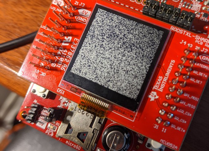
It’ not the result that I wanted, but it is a result. There’s a lot to absorb here. The LCD is displaying nonsense when it should be displaying a hello-world message, and it’s nonsense that’s not moving. The LED at P1.0 also stayed unlit for the entire test, which was deeply concerning.
The LED at P1.0 is supposed to be a sort of rudimentary status indicator that tells me the state of a bit (well, technically a byte I’m using as a bitmask) called VCOM. VCOM is part of SHARP’s standard for their memory LCDs; as a way to prevent the screen from developing a potentially-damaging charge differential, the VCOM bit is set in a command sent at least once per second which reverses the polarity of the two charged plates that control the display. That LED not blinking is at least strongly suggestive that VCOM isn’t changing, so I quickly unplugged the LCD and started going on a bit of a bug safari, looking for the cause of the issue.
Are We There Yet? Exploring the Debugger looking for Flags
As it happens, I don’t particularly understand Creative Code Studio’s interface or operation particularly well. I’m a Jetlabs guy - they don’t pay me to say that, it’s just what I know.
That said, any IDE worth the space it takes up is going to have some kind of onboard debugging, and CCS is not the exception to prove the rule. As it happens, the debugger here isn’t horribly unintuitive, though I’ll freely admit I haven’t quite taken full advantage of it’s features. To use it, you can flash the device using the debug tool, and then step over or step into code as it is executed on the machine while also using tools like the memory browser to check the actual state of known registers.
I started this process working on the assumption that the VCOM LED was not illuminating because I was never reaching the Interrupt Service Routine (a special kind of function) I set up to handle changing VCOM.
Interrupt Flags, MicroControllers, and Toggling VCOM.
If you want to do something once a second, regardless of whatever else is happening, you’re looking for a Timer Interrupt. An Interrupt is a special flag (usually a bit hiding in a register) that indicates to the system that something important has happened. Interrupts take priority, usually being handled by an interrupt service routine, which goes looking for that flag (called a vector), does some special action because of it, and then takes action.
I used a GPIO interrupt to detect keypresses in my binary counter. This is much the same for this project, only instead of interrupting on a button press I am trying to interrupt ever 1000 ticks of a 1MHz timer - roughly once a millisecond. I say trying because, well… you’ll see.
My experiments with the memory browser confirmed I was setting the flag, and the step-through work I was doing seemed to indicate I was entering the ISR, so I started to worry there was something physically wrong with the board.
Wait… did I just burn out the LED? Somehow?
I struggled - for a good couple of hours, to get any kind of responsiveness at all from either P1.0’s LED or P1.1’s LED after that. Part of this struggle was simply getting the IDE to let me flash the board again - I discovered way too late that it can put itself into a debugging mode that has to be terminated before you can ever flash the board again. Even so, I tried all variants of dumb tricks, and convinced myself the LEDs themselves were somehow faulty.
Then, by a stroke of either luck or genius, I checked on the source code for my only other embedded project, BinCounter, and found this lovely command:
PMM5_Unlock(); // DriverLib alias for PM5CTL0 &= ~LOCKLPM5; exits high-impedence mode.
So not only did I run into this problem once before, but I completely forgot about it.
One of the power management options available on the MSP430 series creates a high impedence state for all GPIO pins, which as near as I can tell is done so that the pin can stay in its expected state (either high or low) regardless of what the CPU is doing or even if it’s awake.
However, since this is done the way it is done, you have to manually kick that “lock” out of memory in order to change pin states. I added a few quick lines more or less immediately after GPIO is initialized to turn these pins on, and:
That’s a result.
Nope, It’s Definitely the Interrupt
After that, I put things more or less the way they were, and commented out everything but the code that cycles the VCOM state (in the ISR) and the code that changes P1.0 depending on the state of VCOM. I also added a command right at the head of the ISR that toggles P1.1, meaning that LED should blink at about 1khz. Probably, this is way too fast to see, and might even be bad for the LED.
However, it turned out to be a moot point, as even with the only operation being to bring P1.1 high (rather than to toggle it), the LED never comes on. I’m assuming this means I never hit my ISR. In order to dig into why that is, I’m going to need a lot more documentation on the matter. There’s a textbook I’m planning to order this week that I hope will make things clearer for me.
If for some reason you enjoy Tapestry, PETI, or any of the other projects I’m working on for Kensho Security Labs, and you wanted to show your support financially, your best avenue is via my Github Sponsors account. If you’re feeling the need, I also enjoy coffee.