
Model II, Part 4 - A Year Later, and a Dollar Short
Last Updated: 2023-10-17 05:00:00 -0500
Having finally decided to get off my backside over the last few weeks and make the templating changes that would let me make a proper project page for the Model II, I have decided that this is as good a time as any to go ahead and do a follow up blog post to the series from last summer on the Model II. It’s been over a year since I put that keyboard into use and I used it for most of that year, so let’s talk about what worked, didn’t, and what comes next for that project if I want to really get my money’s worth out of it.
So, About Those Encoders
The Model II specified in a trio of rotary encoders which my firmware maps to either the Mouse X, Mouse Y, or mouse scrollwheel directions. Between them and the use of holding down a function key for a finer movement scale, it was supposed to be possible to navigate around a reasonably small screen; not great for Daily Driver use, but just fine for a planned-ish cyberdeck build I’d still sort of like to eventually pursue.
There’s just two problems with that.
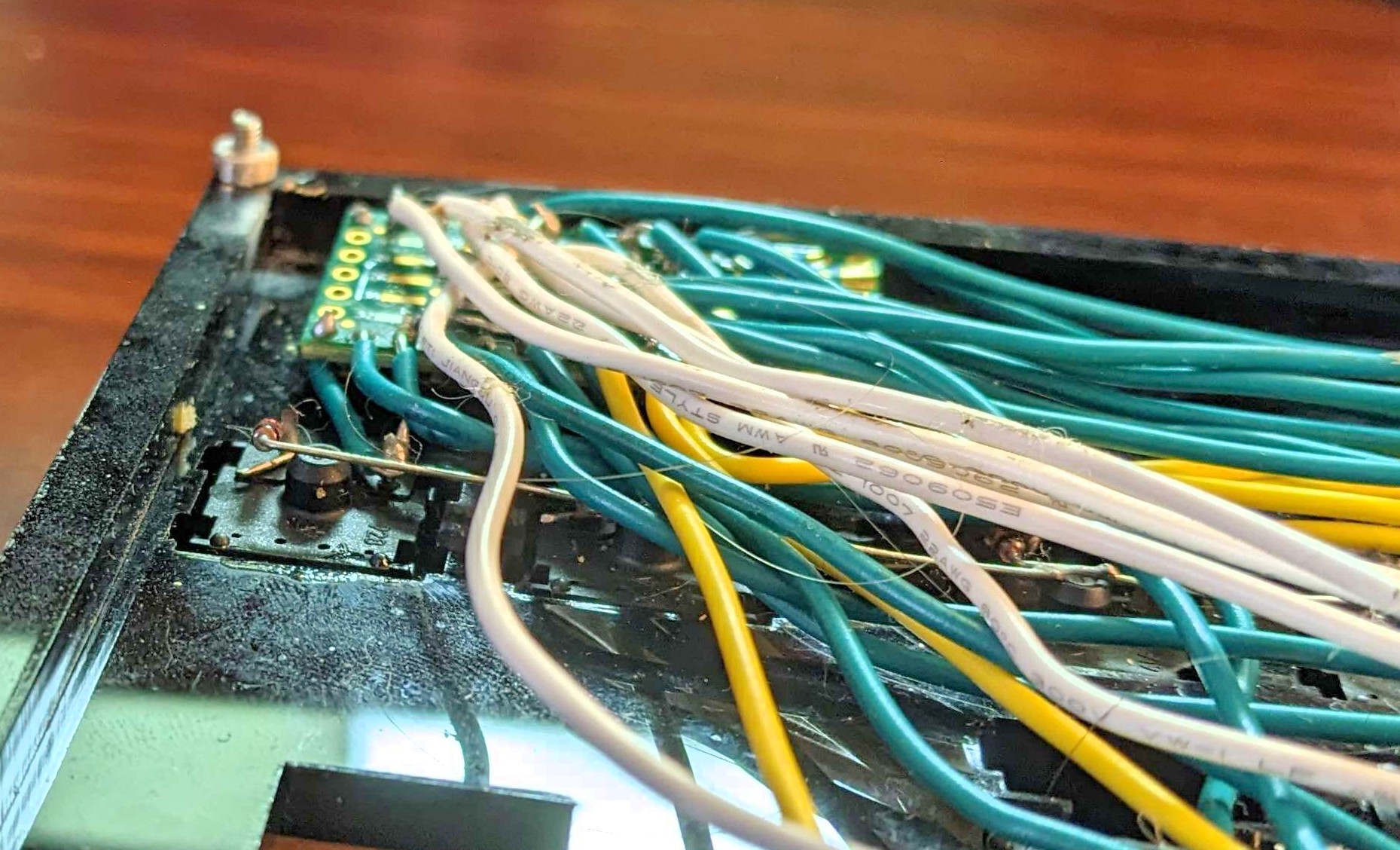
The first is that the placement of the lines that connect the diode grid for the keys to the teensy controller obscures the pads used for the encoders. While all these logic lines went into drilled holes along the edge of the teensy, the GPIO pins the encoders were intended to use are actually pads on one side of the teensy board, and as you can see in the nearby image, the wires cover them up pretty neatly.
Worse, as just one of the many problems caused by the wiring itself, even if I could get in under there to attach new leads without melting anything, that knot of wires is enough that a firm impact on that corner of the board can push the teensy up against the acrylic above it and put it into programming mode, forcing me to disconnect and reconnect the board if I want keyboard functionality back.
The other main problem with the encoders is a problem I seem to run into frequently: I am absolute pants at ordering knobs to go with my encoders and pots. I know the process is parametric, but somehow I always either blow the shaft parameter or the overall OD parameter and end up with knobs I can’t use. Without knobs, it goes beyond just being uncomfortable to adjust these encoders; they’re genuinely hard to turn.
I don’t want to abandon the encoder idea, but it’d take serious rework to make it work. What’s worse, under windows at least, if I send a “mouse” signal using the keyboard (such as by pressing one of the keys meant to map to mouse-clicks), Windows itself seems to get confused and kill the device driver. I’m not sure yet if I can solve for that, but since the main system I wanted the mouse for was going to be a cyberdeck running, most likely, raspbian, I’m not that concerned with it.
A WHOLE Spool of Solder?
If you’d had a spy camera in my office for most of the last year, or worked for my day-job employer, you’d have caught me more than once in the middle of a Teams call, flipping my keyboard over and applying the odd gob of solder. That was, by and large, because of the horrifying mess I made of the free-wired diode network.
Free-wiring is an acceptable way to build a keyboard, but it has to be done right (it wasn’t) and it has to be protected from shock (it isn’t). It probably was never appropriate in the first place for a keyboard I intended to fit into a briefcase and carry around at random, but I thought I could at least get away with it for the first several months. I was wrong. Most weeks involved at least one bad lead, and the main culpret wasn’t even what I thought.
There are essentially three kinds of joints in the wiring harness right now:
- Direct connections between a wire and a device. Amazingly, though there are hundreds of them, none of them have failed.
- Leg-to-leg connections on the diode chains that make up the rows. One or two of these have failed, but not many. Even when they have failed, spring tension (for lack of a better word) tends to keep the diode rows in good contact. Ironically, this actually makes them harder to diagnose when they do happen.
- Wire-to-wire connections between the wire column and the wire that takes that column’s signal to the controller. These fail constantly and with unpredictable results. Sometimes it takes out the whole row, sometimes it causes double-keypresses, and it’s often intermittent entirely.
Both 2 and 3 have solutions, but those solutions involve a lot of rework. I think to do it right I’d have to completely desolder the wire columns and their signal leads, and rework both from braided cable instead of solid-core, so that I get better solder penetration into each joint and something more stable, then put it all back. Assuming I want to solve it with freewire, anyway - more on that a little later in the discussion.
The diodes barely need a fix. If I was to fix them, they’d be fairly easy; I could actually twine the legs together instead of laying them across each other, or perhaps even just reinforce each of the now-soldered legs with a bit of electrical tape or some other mechanical connection.
Unstable Stabilizers
I talked quite a bit in part 3 of this series about the problems caused by how thick I made the keyswitch plate; the main piece of acrylic in this keyboard which holds all the keys in registration with each other. One of those problems, which I severely under-estimated the full impact of, was just how unreliable it ended up making the stabilizers. This didn’t matter as much as I thought it would for keys like enter, shift, and so-on, but for the spacebar it was a serious problem. The spacebar I was using wasn’t properly designed for the style of stabilizer I was using, and it would have still worked okay, except that those stabilizers also didn’t work well with the plate. End result, the space bar is almost always slightly twisted, impinging on the decorative wooden face-plate or causing the switch to misregister inputs events.
Since I write in the English Language and I code in whitespace-dependent languages, this is a small problem, to state it very very mildly. It becomes workable after a while; I eventually learned to hit the key very near the center and using the opposite thumb I normally would, which solved most of the problems. Ideally though, it would be nice to solve that problem overall.
Solutions to All Of These Problems
The real lession of Tapestry for me was that I should never jump feet-first into a solution for a technical problem, and it’s become my habit over the last year or two to stand well back from a broken design and come up with two or three ways to fix them, and weigh the pros and cons accordingly.
Solution 1: Remanufacturing the Switch Plate
The vendor I used to cut my acrylic switch plate will also cut in other materials, like powder-coated steel. Steel could be much, much thinner and have the same rigidity as the acrylic board, with the advantage that the stabilizer parts and switches would sit better in the panel. This is obviously extremely desireable, but I can’t just replace that: I would have to have new side pieces made, and since I haven’t checked the inventory in a while I might have to have a new back panel made too (which would involve ordering new screws). On the other hand, this would also offer the opportunity to change the design of the area around the space bar slightly to provide the right kind of stabilizer mounting in those positions. I could then take full advantage of that to solve all of my fitment issues in one stroke.
This also has the advantage of offering more space for the wiring, but a very real cost in terms of the money spent on having the new parts made and shipped to me. There are other laser cutting vendors out there who might be cheaper, but given what I’ve already spent on this project I get extremely reluctant any time a solution is going to incur a new cost. In the long run, I probably have to do this step regardless of which of the other two solutions I pick, as it would make both of them easier.
Solution 2: Replacing the flying wires with a printed circuit board
My first thought, about four months ago, for a long-term solution to most of the stability issues plaguing the keyboard, was to create a Printed Circuit Board. PCBs are the standard for electronic devices now for a reason. They provide their own source of mechanical stability, and to be honest, they let me pack a more complex wiring diagram into a smaller space than my skills at managing a flying-wire solution ever could. If I designed it right (or designed the switch plate around it, possibly), this would also let me solve weird problems like access to the pads for the encoder headers. Yes, it’s less repairable, but it’s also just generally going to need less repair. Hell, if I put my ducks in order, I could even provision it to let me add the desired “activation” LEDs under the capslock and numlock keys.
There’s just a small number of problems, mostly revolving around mechanical sability. I can’t just redesign the top switch plate and the PCB without also redesigning the rest of the case, and I’d have to do so in a way that is mechanically resillient. This can be easier said than done when I can only design a part in two dimensions.
It’s also the most costly possible solution no matter how I slice it. Since I don’t have the ability to edge a board at home, I’d have to buy all the necessary materials and consumables and tools. For the same price, I could probably order a batch of these boards from my usual PCB manufacturing partner, but then I’d be stuck with a large number of spares, of a keyboard design nobody else is likely to ever want, at an exceptional cost. By the time I paid for PCB milling and the new lasercutting both, I could probably very realistically expect to spend almost as much as it would cost me to simply buy a medium-grade mechanical keyboard pret-a-portier. It’s still the most attractive solution, but I just can’t afford to actually do it.
Solution 3: Remanufacture the Wiring Harness
I could completely desolder the wiring harness of the keyboard, using the existing harness for an example and measurements, so that I could build a new wiring harness out of braided cable, and make all the connections more secure. That’s the cheapest (though probably most time consuming) option for a solution. It’s still going to be prone to random failures, though, in ways that a PCB won’t. And it still leaves me with a crowded case that can’t be protected from picking up dust and debris.
In the end? I’m definitely going to have to go the remanufactured case and PCB route. It’s just a matter of actually bringing myself to raise and spend the necessary capital. Even as a present to myself, it seems a bit extreme when I’m still trying to get my synth to a functioning level of completeness and when I need to be raising the money instead to get the Revision D PETI dev kits onto the market. Maybe come spring we’ll do something with it. In the meantime, perhaps a future livestream will feature the design work needed to pursue these.
If you wanted to show your support financially for Arcana Labs projects like the Model II or PETI, but don’t need a virtual pet development kit, your best avenue is via my Github Sponsors account or by making a one-time donation to Arcana Labs via Ko-Fi.com or through other avenues detailed here. Supporters also get access to a special patrons-only section of the Arcana Labs Discord Server as well, and new bonuses are soon to be introduced on the github side!