
PETI: What is a Byte? Why are those Letters Backwards?
Last Updated: 2020-10-02 20:15:00 -0500
Last time we talked about PETI, I spent a few hundred words bloviating over getting trapped in a state of not having an ISR to handle an Interrupt that I couldn’t resolve because it didn’t occur during debugging, and thus couldn’t be identified. To be honest, I still haven’t identified the relevant interrupt. What I did do, though, was heavily troubleshoot my SPI_WriteLine function, resolving whatever issue was raising the interrupt in the process, so close enough.
That issue turned out to be yet another artifact of having “ported” code by copying functions and values around. I was attempting to address a specific register that simply didn’t exist. Oops. Finding the correct name was a simple matter of studying the documentation, and once that was done I had picked the lock on the ISR trap.
This still didn’t resolve my display issues, and it was at this point I fell down a rabbit hole.
Bytes, Words, and Stupid Developers
The MSP430FR5994 microcontroller is a 16-bit RISC system. Knowing that, the memory browser in Code Composer Studio, the IDE TI makes freely available for working with these devices, defaults to 16-bit binary representation of memory addresses. I have been computing for years on the understanding that a byte is eight bits, but somehow, I convinced myself that’s merely a convention.
The long way around this story is that I somehow convinced myself that when the documentation for DriverLib said that the SPI_transmitByte() command accepted a byte to output to the target device, it was taking a 16bit word. Fortunately, I didn’t spend long adapting my code to implement this; an immediate test didn’t make the display work any better than it had been before, so I checked the source for the relevant portion of driverlib and sure enough, it meant a proper byte.
So, two more hours down, and without a clue as to what was going on, I added a breakpoint between all of the SPI transmit commands within my writeLine function, and copied the contents of the TX buffer (UCB1TXBUFW) by hand onto a buddhaboard to compare them against Sharp’s programming documentation for the memory LCDs.
Doing this actually let me see some bugs that, amusingly, weren’t the root cause: while I had, correctly, defined a variable to hold all the various control bits as bitmasks, I didn’t reference them everywhere, and before the main timer interrupt loop started, this meant that VCOM was briefly in the incorrect value, which lead to passing junk commands to the LCD. This still wasn’t the issue, but I couldn’t see anything else in the traffic that was wrong once this was corrected.
Checking Your Assumptions: Code the Specsheet
Early on in this project I had convinced myself - based on discussion of other devices - that my intuitive understanding of SPI chip select being HIGH to control a target device was flawed, and that the convention was low. I even reimplemented my code rather aggressively to accept this change, which initially seemed to show promising results - suddenly the screen was actually clearing when I turned the device on. This must have been a fluke - I had never sent the correct clear command until today, due in part to the VCOM error.
Of course, in my despiration to understand the command issues I pulled up the spec sheet for the exact SHARP MLCD unit that is part of the project and was studying it, looking for commands that might be structured differently than the rest of the product line, when I noticed that the fancy graphs seemed to show SCS (signal, chip select) coming high for writes.
Okay, fine, change one function and WE ACTUALLY GOT TEXT OF A SORT!
Why do backward Latin characters look so much like Cyrilic, anyway? From here, I was able to uncomment the rest of my print functions, and wouldn’t you know it, everything wrote out fine.
Hunting the smaller bugs!
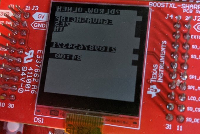
I had ported my font from the same original repo I had originally found my code, and for a brief moment I considered writing the font myself to correct the printtext function. As you can see, all of the chiral characters are being represented backward, even though the character order itself is correct. This is because of how the values for the characters were arrived at by the original developer - writing the characters out as byte-width binary numbers and then recording the hex.
Since both the MSP and the LCD are little-endian, I can only assume that the intention was to flip the characters around in the send, which the eUSCI system can do pretty well all by itself, since it will let you switch the endianness more or less on the fly (handy if you don’t want to make sure everything on your SPI bus is speaking the same endianness). I’m far lazier than that - and I realized that I would want to build images in the orientation I wanted to see them in on the screen - so instead I found a function that uses shift operations to reverse the order of a byte. The writeline command, as the most primitive part of the process, now references that for each content byte, which flipped the letters around the right way.
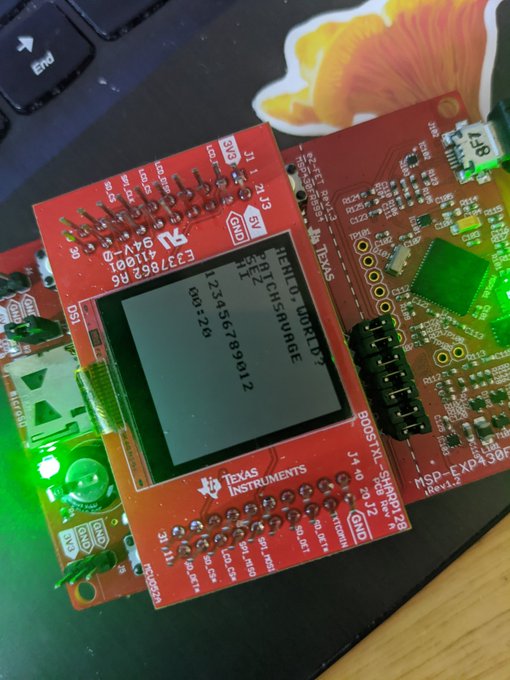
The colors were likewise very easy - writelines now basically takes the inverse of the response from that reverse function. This is because the MLCD treats a high signal as a white pixel rather than a black one.
A little light tweaking also made sure that the printText function was correctly writing a lineBuffer the full width of the screen, and that the writeline command was sending the entire buffer.
All these changes took maybe half an hour, compared to the proceeding several hours of debugging, and left something much nicer:
Since the PETI codebase isn’t public (or even technically extant yet) and I can’t help but feel I would have avoided a lot of this hassle if such a thing existed previously, I went ahead and posted my code to github. My Repo does not, however, have driverlib or any of the MSP430 headers available. If you want to play with it, install CCS and driver lib then just copy my files into a new project that uses those features. I didn’t submit it as a PR because it showed startlingly little resemblance to the original codebase once it was done, and I was using different hardware to start with, so it made more sense as a unique repo. I also changed some strings.
October can be a spooky month! If for some reason you enjoy PETI, or any of the other projects I’m working on for Kensho Security Labs, and you wanted to show your support financially, your best avenue is via my Github Sponsors account. I also have a few copies of my novel, Sanity Line, left, that I have been offering for sale with a personalized message inside, so send me an email if you want to talk about that.