
LabNotes: Rebottling the Blue Smoke
Last Updated: 2021-05-04 23:00:00 -0500
24 hours ago, I was absolutely certain I had attained a dubious electrical engineering right of passage, and blown up my first development board. I was certain of this because I had tested it extensively. Twelve hours ago, I learned I was wrong.
Yesterday I took delivery of several components I was going to need to move this project forward, including two new MSP430-EXPFR5994 development boards, because I was absolutely certain I had somehow fried GPIO ports 5 and 6 during earlier testing and the device itself was damaged.
How This Conclusion Was Reached
As you may recall, I mentioned a week or two ago that I tested this directly:
I’ve even written a few short programs that do nothing other than drive those pins into the state I care about and hold them there, and nothing. It’s likely that I damaged the GPIO ports controlling those pins, but the upshot of the matter is that I can no longer use the current exemplar dev board to move forward.
I want to talk about that a little bit more, because while we’re sort of skipping to the end of the story, it’s important for now to understand a flaw in my thinking. PETI is written using the driver library TI themselves provide for the MSP430-FR5994 microcontroller. This provides an API-level interface for dealing with a lot of common tasks on the device peripherals such as the GPIO ports and eUSCI, and I decided to use the driver library for two reasons:
- I’m a wee baby dev when it comes to C. I understand the basic premise of performing bitwise operations against specific registers, but I didn’t want to agonize over constantly looking up the memory map tables in the developer docs and performing bitmasks, because I want a working product this side of my retirement, and;
- The intent of the project is to open-source the code and leave it as a jumping off point for other aspiring hardware hackers and nacent makers to modify, play with, and use for examples. Therefore anything that’s not part of the hidden puzzle functionality should be as unobfuscated as possible.
And when I performed my test, I did the following using that driver library:
- Drive High P1.1 which is an integrated LED as proof of concept.
- Drive high the “damaged” pins I was concerned was misbehaving.
Since the LED came on but the pins did not come high, and all the pins that did not come high were in the same two ports that I accidentially overvolted, I assumed physical damage.
What are the odds?
Over the course of my regular tuesday building stream, I discovered that not just my old board, but the two new boards I had also manifested the same problem. What was worse, upon testing further with some GPIO ISRs I already had configured, none of the input pins on any port higher than P4 was working! What are the odds that all three boards had the same physical defect?
Practically nil.
As a simple test we go one level further toward the copper and I set the pins high using direct assignments to the registers that control their output direction and state. Magically, this resolves the issue on both the new boards and the original hardware, so there’s $50 CAD I spent because I forgot to check something. Probably not the first or last time!
We need to go deeper
It was time to break out my friend the debugger. I don’t like debugging this device in CCS. I’m learning that I don’t like CCS at all, but it’s also difficult for me to think in bitwise fields of hex representations of the state of individual words in memory. I always spend twice as long as I should finding the value I’m looking for in the memory browser, and then I’m quite sure I don’t properly understand it.
As part of my debugging I step into the code where I call the driverlib API to set the direction of the pins. As functions go this is probably one of the ones I understand best at the register level, and the raw C code of what it is trying to do is also pretty clear:
void GPIO_setOutputLowOnPin (uint8_t selectedPort, uint16_t selectedPins) {

    uint16_t baseAddress = GPIO_PORT_TO_BASE[selectedPort];

        ...

    // Shift by 8 if port is even (upper 8-bits)
    if((selectedPort & 1) ^ 1) {
        selectedPins <<= 8;
    }

    HWREG16(baseAddress + OFS_PAOUT) &= ~selectedPins;
}
It’s pretty easy - look up the human-readable name of the port as an index in the array of addresses, get the memory address, update the mask by bit-shifting it if needed (because the ports are controlled by 8-bit words that are actually stored in 16-bit memory, then write to the register. Simple?
And I also know from picking up my documentation that the correct address for P6 is 0x0240. The debugger, however, tells me that the value is 0xFFFF, which I don’t trust because:
- I don’t trust the debugger, and;
- After the operation the value of 0xFFFF is unchanged, so it clearly didn’t do anything.
And because of this I sit here baffled for a while. For a moment I suspect it’s possible that I don’t have the right symbol pre-defined to tell the compiler which set of headers to use to define the memory map, and I dismiss that, because it’s correct.
Back up and think through that again.
Now I’m not going to lie. My answer, ultimately, was googling the problem. But as an exercise in reverse construction I’ve figured out now knowing the problem how I could have seen what happened, and the first thing I should have done was trust my interpretation of the changing memory address because it was absolutely correct, and the value in the register at 0xFFFF was not changing simply because it was already in the correct state, and I am a fool.
So, why did the value change?
If I’d been thinking clearly and not trying to rush a working module out of the door, I could have stopped at the address changing in memory, and tried to figure out where the 0xFFFF value was coming from.
As it happens, there’s a block in the same chunk of c that defines the GPIO API which is responsible for building that base address mapping:
static const uint16_t GPIO_PORT_TO_BASE[] = {
    0x00,
#if defined(__MSP430_HAS_PORT1_R__)
    __MSP430_BASEADDRESS_PORT1_R__,
#elif defined(__MSP430_HAS_PORT1__)
    __MSP430_BASEADDRESS_PORT1__,
#else
    0xFFFF,
#endif
Which is basically an at-compilation chunk of logic to check and see if some symbols are defined earlier in the build, and construct the GPIO_PORT_TO_BASE address array accordingly, failing over addresses for undefined ports to 0xFFFF. This means, perhaps unsurprisingly, that those symbols are not defined for me.
But since I have the right main symbol saying “this is an MSP430FR5994”, where in the hell did things fall down?
What else isn’t mine here?
In addition to the driver library there is an extensive set of includes baked into CCS by default which provides convience pointers to all the register memory addresses on the device, itself referenced by including <msp430.h> into the source. I’ve been using this all along and never really thought much of it. It’s a vendor-provided library.
But just for giggles (and because we’re doing reverse construction and I already know what we’re looking for) let’s think this through:
- The developer includes msp430.h and has a predefined symbol in the project settings that specifies this is an msp430fr5994.
- We can grep that symbol in the msp430.h file itself to determine how it is used, and that is to include a specific header file for the MSP430FR5994,
msp430fr5994.h, and what’s more: - we inspect that file’s DIO section we find that in fact the symbols for the ports greater than 5 are not defined.
But this worked before
Yes it did. I had a working version of the PETI source code published in December 2020 which worked perfectly fine. However, I constructed that version in CCS 9.x. Between now and then I blew up a whole computer and as a result have a fresh install of CCS 10, and between 9 and 10 the header files must have been changed. I know they were changed because TI themselves say so, but since I wasn’t including any of TI’s driver files in [my repo] I didn’t have a good way to compare to a known-good file. Googling the problem helped (and is ultimately how I solved it), but based on comparing the new file to what the driver library expected it would also have been possible to take the memory map from the documentaiton and assign the correct values within the header file, though that would have been a lot more work.
Plug the Toaster into the Wall, Buy a Loaf of Bread
And make toast.
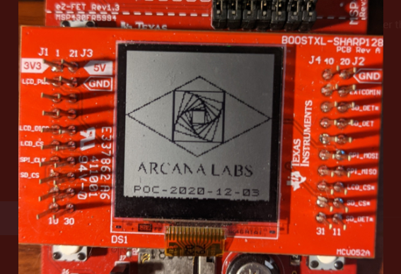
That’s all I wanted to do two weeks ago when I thought I’d blown up the board, though looking at it now in the clear light of day we gotta clean up that bitmap a bit.
What’s next?
Up next is solving the GPIO problem again by re-creating the controller daughterboards. I have enough components on hand to build at least two, so I’m going to try to desolder the existing boards, verify that there’s no voltage leaks or anything with the board itself, then solder one up using my new, more precise iron.
If that doesn’t work (and, honestly, even if it does) I’m thinking of having a half dozen or so of the daughterboard for the buttons made by DKRed just as soon as they fix whatever bug in their ordering system is preventing me from ordering from them.
PETI is a major project intended to design and construct a virtual pet from Open Source Hardware and Software. If you would like to support the development of this, or any of the other projects I’m working on for Arcana Labs, and you wanted to show your support financially, your best avenue is via my Github Sponsors account or by making a one-time donation to Arcana Labs via Ko-Fi.com or through other avenues detailed here. adminops@Polaris:/var/www/arclabs/jekyll-test/_posts$