
Lab Notes: Inventing SPI Video Capture with a New Tool
Last Updated: 2022-03-15 06:30:00 -0500
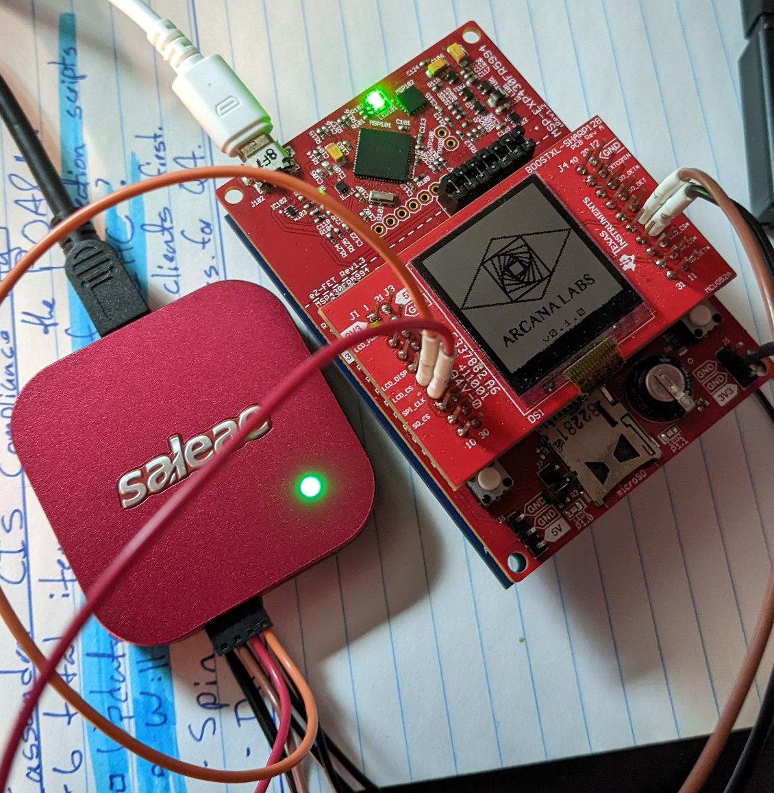
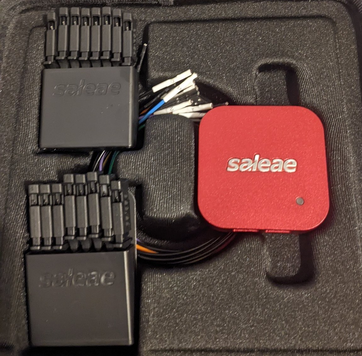
One of the great truisms of making things (the precise definitions of ‘making’ and ‘things’ being surprisingly flexible) is that there’s always room for a nice side project, and since the last update on PETI, that’s exactly what I’ve been working on. A short time ago I acquired a Saleae Logic 8 USB Logic Analyzer, and while it’s sort of pushing the envelope of what a logic analyzer is used for, I decided to take the opportunity to stretch its functionality into a sorely needed utility - video capture for PETI’s main display over USB.
Why Video Capture?
If you’ve been around the lab for a while you know that I frequently work on PETI during live streams on my twitch channel; almost exclusively so, in fact. Up until this point - in fact, up until pretty late last night - the only way I could let people see what was going on with PETI and its display was to point a webcam of some sort (usually a pressganged cellphone) at it and hope the focus would hold. It’s grainy and off-putting, and I’m not the biggest fan of the way it looked, but it was the technology I had. However, the logic analyzer was going to change all that; and a direct read was going to look much nicer.
How Logic Analysis Works
The Saleae has a lot of features - more than I can cover and probably more than I can use - but the primary function of a logic analyzer is to take an independent measurement of a digital signal directly from the medium its being transmitted on. In my case, this is achieved by pinning probe leads to certain pins on PETI (and, in a later hardware version, by simply connecting directly to the expansion SPI header with one probe on the LCD ChipSelect pin). These leads read the same electrical signals that the LCD itself does, and display as a graphical waveform in the desktop UI.
Because the Logic8 is a USB logic analyzer, and its mode of operation is to simply use my workstation as most of the analysis gear, Saleae have built a rather responsive and expansible UI called Logic2. This was sort of the deciding factor for me: logic 2 is readily expansible in both python and c. Convenient, that, since that’s basically my entire programming skillset.
So we’ve got SPI Bitstreams. Now What?
Longtime readers are familiar with the fact that I like to emulate machinery in object-oriented code, like python-enigma, and I took the same approach when designing my interpreter. Logic2 has the option to run what is called a High Level Analyzer (HLA), written in python, on top of a protocol analyzer like their SPI analyzer. The SPI analyzer turns the waveform data into a bytestream, and an HLA can do further analysis on top of that. This took a far bit of work to get right and I ultimately had to spend two livestreams working on it. Let’s have a deep-dive look at how that works.
AnalyzerFrames in, AnalyzerFrames Out
Unsurprisingly, there’s a whole API built into Logic2 that can be leveraged by an aspiring HLA developer. I didn’t have to deep dive into anything, at all, to get this to work - in point of fact, the HLA I wrote is some of the most terse, compact, and straightforward code I’ve ever written that wasn’t some one-off tool for work.
The basic concept is this:
- When an HLA is first invoked, it instantiates your custom subclass of their HLA object with an
__init__, which of course will do whatever you set it up to do. - Each time a frame is generated by your protocol analyzer (
SPI, in my case), an AnalyzerFrame is passed as the argument todecode, and python being python you can have that done any way you want.
What I chose to do was to have my HLA create its own sub-object, which was an OOP emulation of a Sharp LS013B7DH03. In truth it’s a general emulation of existing and hypothetical SHARP memory LCDs based on this programmer’s guide as a generic specification.
In my very specific case, the way this worked was the following:
- If the incoming SPI frame was to enable the display to read, we’d set a flag on the display object for that purpose.
- If the incoming spi frame was to disable the display from reading, we’d call a function to flush the stored image to disk.
- If the incoming spi frame was data, we’d take that data and perform some mild interpretation on it before passing it to the display object for further interpretation.
Data Orientation Is A Problem
In general computing, for most people’s day to day application, there’s so much standardization and convention happening that we never usually have to think about things like encoding schemes or byte order, at least on the mechanical level. If I want to send a lengthy writeup on how I chose to spend my monday night, I have only to consider my wording and make sure that my ideas are roughly parsable, and then as long as the person on the other end speaks my language, the message will get where it’s going.
This is less true with SPI communication. While there are general practices in SPI, and vague conventions, the fact is a lot of different factors can come into play, such as:
- Whether it is the digital-high or digital-low voltage that corresponds with chip select being “active”,
- Whether the voltage on the MOSI and MISO busses should be considered a bit when the clock’s signal is on its leading edge or its trailing edge, and;
- Whether you should send the least significant bit first, or the most.
This took some experimenting to get right for my case, which was:
- CS High
- Data on trailing edge, and
- Least Significant Byte First
And still, for whatever reason, when I was interpreting the bytes into the data stream I was doing so backwards (an easy enough fix in code). Be that as it may, once we got past most of the logic flaws, it was pretty easy to beat on the SPI settings until they looked right. Logic2 - the analysis software that we’re using here - will re-run analysis on your capture for any analyzer if you change the settings, automatically, so once I was confident I had a good capture in the first place (just the first few seconds after a reset to be sure I captured PETI’s boot screen), it was just a matter of changing all the parameters in the dropdown menu until the image looked right, as below:
Better, my settings seem to persist between sessions, so as long as I don’t have to take that analyzer down for some reason, I can pretty much use this indefinitely.
Disk I/O, Bane of Responsiveness
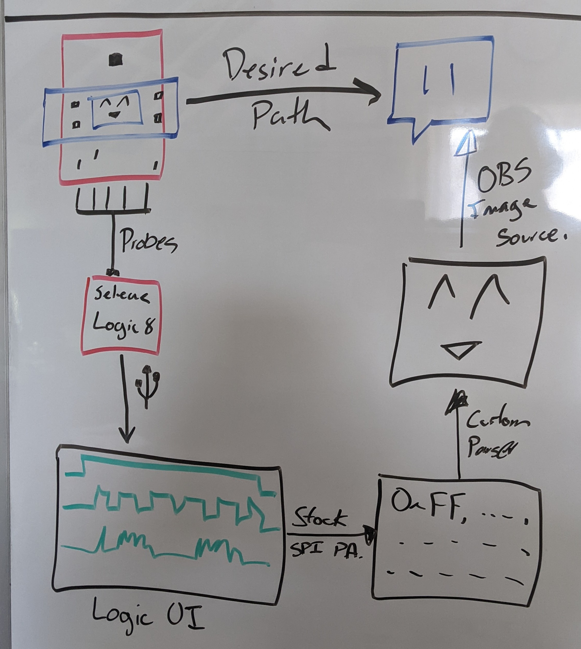
I went into this project expecting the “video capture” framerate to be a little poor. For one thing, PETI only updates its screen roughly twice a second in the first place (not accounting for the actual display write cycle, around 30-50ms). For another, my plan (as illustrated here) was to simply have my HLA spit out an image file, which I would then import into OBS as an image source, and I already knew from my experiments with [the sticker switcher] that there is a rate limit on how quickly you can change that image before OBS will refresh it as displayed. That said, my initial testing showed that I could swap out that image roughly twice a second without completely choking OBS, and the SPI analyzer ran in more or less realtime as near as the human eye could tell, so I had confidence.
And then, the real world intervened. When I added the HLA, suddenly analysis slowed to a crawl. We’re talking easily taking upwards of 10 seconds to run over a .7 second analysis. Not ideal, not by a long shot.
The constraint? Disk IO. Pentacost, my workstation, uses a spinning rust drive for the main linux install. There’s a real constraint there with writing even a relatively small bitmap in, especially when the original logic was to flush that image into memory every single time chip select went low (which in the current PETI firmware is every time a single row of pixels was updated). Write the whole screen at once, like I do with the splash page? Write 128 128x128 pixel PNGs to disk. Oops.
Fortunately the solution here was also made easy by the APIs of Logic2 itself; each incoming AnalyzerFrame from the SPI analyzer has a wall clock time property for both the start and end of the frame. All I did was add a check to make sure that the flush command will only flush if that wall clock time is some configurable number of milliseconds (250 seemed to do the trick) after the last time it did a full flush before trying to write the image.
While there’s still a small amount of lag in the system between what I’m seeing on the toy and what shows up in the capture, that’s actually not bad.
Share and Share Alike
If I had to build every tool I used, we’d still be somewhere in the “Three Plates Method” phase of development here at the lab, and that’s just not acceptable. I only took the time to write this plugin because it seemed not to exist already for Logic2, and as near as I can tell I’m still the only one who’s developed something like this. Logic2 has a pretty extensive in-application extension library and the extensions are one-click installable. What’s more, anyone can add their extension to that library, as long as they have a github repo for the extension they wrote.
In my case there’s just one catch. I used PIL to handle the actual encoding and saving of the image, and PIL is a third-party library, which is currently not supported in Logic2. Saleae’s support have published a workaround of a kind, but it’s a code-level change so it wouldn’t necessarily just work outright if I published to their storefront. I will, the very minute they add support for external dependencies.
That said, this is still an extremely useful tool, so I’ve published the source code as well as having made it part of the PETI Helpers toolbox repo via git submodule. Depending on your install practices you may have to edit line 5 of HighLevelAnalyzer.py to get it to work for you.
What’s Next?
For this project, probably nothing for a while, but there’s no shortage of missing functionality that could be packed into this thing, like all of the following for example:
- Ability to write successive files into a directory instead of continuously overwriting a single file (useful for screenshot generation for, say, a manual).
- Ability to record successive frames into a GIF or other animated format instead of continually overwriting a still image.
- Ability to specify a scale value to make the output resolution higher than the input resolution - this is very useful for displaying the smaller screen sizes on larger displays without anti-aliasing making a mess.
Finally, a Recommendation
If you’re getting into electronics at all, especially embedded development, I strongly recommend that you consider a logic analyzer as a relatively early tooling purchase, and you could do a lot worse than the Saleae Logic8. There have been periods throughout this project where having an analyzer to hand would have made things much clearer, and I’ve called that out in the past - as well, this will help with future goals such as the development of the expansion SPI system. In terms of feature richness, having the USB connection and all the extensibility that implies also makes something like the Logic8 attractive by comparison to a much more expensive benchtop unit that may or may not even offer the same immediacy of analysis.
Granted, this assumes you’re doing work fairly similar to me. If you’re mostly working with analog electronics, maybe a dedicated oscilliscope will suit your purpose. Where I dabble in both, the logic8’s analog measurement functions are just fine for me, though.
Finally, a note on quality: this thing seems to be really well made for what it is. The Saleae team are constantly making both hardware and software improvements to the entire line, and the cables it came with frankly have the best connectors out of ANY of the test leads in my selection - never mind the packaging, which was top flight. My only real concern is that when it’s run for hours at a time it seems to get pretty hot, which is to be expected. If I were really worried about it, I could always rig up some sort of cooling solution.
Granted, my analysis of its usefulness to me is colored by the fact it appeared to be the only real solution to my problem and that I was fortunate enough to be able to work with their support team to get it under an enthusiast pricing scheme. Honestly, for its feature-richness, it would have been worth the full price, but that price would have just been outside my reach as a hobbyist outside of a very special occasion.
They also offer a variety of options on their website and I recommend you investigate those fully.
PETI is a major project intended to design and construct a virtual pet from Open Source Hardware and Software, and to encourage others to modify and tinker with similar projects. If you would like to support the development of this, or any of the other projects I’m working on for Arcana Labs, and you wanted to show your support financially, your best avenue is via my Github Sponsors account or by making a one-time donation to Arcana Labs via Ko-Fi.com or through other avenues detailed here. Github Sponsors also get access to a special patrons-only section of the Arcana Labs Discord Server, where we talk about the ongoing super-secret project.